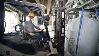

During mechanical handling, raw material often becomes contaminated with tramp ferrous and nonferrous items. This metallic contamination may come from a variety of sources. Incoming products may contain contaminants from the transportation vessel used to deliver the product. The contamination may originate within the plant due to material processing, grinding, crushing, or general abrasion.
The fact is that ferrous metal contamination damages process equipment and compromises the purity of products that must then be scrapped or sold at less than full value. To reduce or eliminate these costly operational issues magnetic separation and detection equipment is highly cost-effective and reliable.
The use of magnets for removing ferrous contaminants in an industrial environment first began in the USA in the early 1940s when Orange F. Merwin developed a flat magnetic product to help farmers trap and remove metal contaminants from their grain chutes. At the time, unwanted or tramp metal in the grain flow often created a spark that would ignite the explosive dust causing fires, sometimes with catastrophic results. Orange’s early version of today’s plate magnet was a huge success. This led to the founding of Eriez Magnetics, which remains after more than 80 years the world’s authority in magnetic separation solutions for industry.
Magnetic separators will remove all types of ferrous material such as nails, rust, scale, bolts, welding rod and other contaminants from dry or liquid products. Metal detection equipment, often introduced in the flow lines later, will indicate trapped ferrous and nonferrous materials such as brass, aluminum and stainless steel.
MAGNETIC SEPARATION
There are broadly three ranks of tramp iron magnets suitable to remove small and large ferrous materials, and that are used in bulk handling applications:
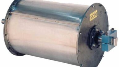
- Permanent suspended magnets
- Suspended electromagnets
- High technology superconducting coil
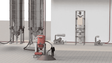
The ideal position is for a suspended magnet to be placed in line with the conveyor, over the head of the pulley. This allows the optimum extraction of ferrous metal from the material. As the material is discharged from one belt to another, the material opens out and the ferrous materials are more efficiently extracted from the bottom of the burden and removed by the suspended magnet.

The other option is to position the suspended magnet in a cross-belt position, i.e., at a right angle to the conveyor movements. In this set-up the magnet attempts to extract the ferrous material directly through the bulk of the product. To obtain the same efficiency as an in-line system, a stronger magnet is required as its effectiveness is tempered by the depth of the burden and the speed of the conveyor belt. Small ferrous items may also remain trapped under the burden.
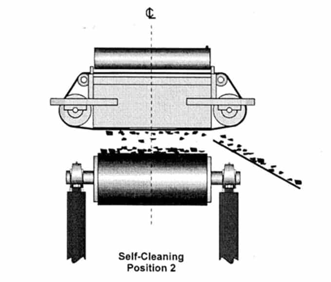
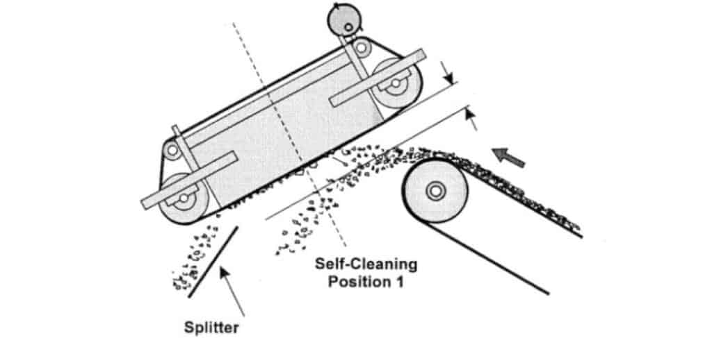
Two options to discard the tramp iron are normally available. In the case of low incidence of tramp iron in the burden, a manual clean solution would be sufficient, depending on the access to the equipment. In the case of regular occurrence of tramp ferrous material and for installation that require automatic extraction, the solution is a self-clean magnet, where a heavy-duty conveyor belt carries the recovered items away from the material and out of the conveying system. There are two main design configurations of permanent magnets: a low gradient type and a high gradient type. The low gradient center pole unit is suitable for high magnetic susceptibility iron shapes, such as bars, bolts, cans or concrete reinforcing iron. It is not suitable for lumpy iron. A high gradient outer pole design (also called opposite pole) is suitable for applications for all shapes of tramp iron and particularly useful for crusher protection.
The ferrite magnetic core of the permanent magnet consists of one large stack of ferrite blocks as a big bar magnet. A steel backbar is added which greatly increases the magnetic material efficiency by concentrating the field in a specific direction. A lower gradient magnetic field will lift iron relatively slowly, whereas a high gradient magnetic field will lift iron quickly.
Although the two magnets have the same cost of materials an outer pole magnet is much more difficult to build and, therefore, more labor intensive, resulting in higher manufacturing costs. However, these can be found necessary for specific applications. Conversely, it is possible to have the magnet too strong for a particular application and in this case a center pole magnet would suffice.
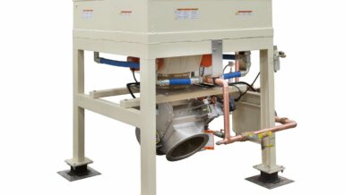
For a more powerful magnetic separation solution, the use of electromagnets becomes essential. A standard electromagnet is typically made of a copper or aluminum coil immersed in oil encased in a steel box. To maintain the strength of the magnetic field the magnet needs to be kept as cool as possible. The parabolic shape of the field produced by electromagnets makes them ideal for deep penetration of heavy burden depths conveyed on troughed belts or concentrated in a narrow flow and this at a higher suspension height.
The choice between an electromagnet and a permanent magnet will depend on the application.
When a high force density field is required at a particular distance, an electromagnet could prove more efficient. For example, when an electromagnet has a force density of 10 k dynes at a distance of 375mm, a conventional permanent magnet would be approximately 3 times the weight and twice the physical size of the electromagnet to give the same force density at the same distance.
However, the following need to be considered: a strong electromagnet will remove long tramp iron from deep within an iron ore burden, but due to the high gradient field it will also remove the less susceptible ore product from the top of the burden, which is to be avoided. A weaker, low gradient permanent magnet may have a similar field strength at the point where the long iron is extracted but, as this type of low gradient field increases more slowly the closer the burden gets to the magnet, the field will not be strong enough within the burden to lift the ore.
Permanent magnets are much more adaptable. A permanent magnet can easily be built to any length, within reason, to give a wide flat field. Electromagnets usually have a more centralized field due to the concentration at the core, making the field at the edge of the magnet weak. Correctly applied, permanent magnets can be more efficient and cost effective than electromagnets.
Other considerations in favor of the permanent magnet in a bulk handling environment are that they do not emit heat and therefore can be used in underground installations. In addition, the cost of installation is relatively low as the suspension height itself is low.
For an even stronger field and very specific installations superconducting magnet can be used. A superconducting magnet is a superconducting coil made of special wire housed in a vacuum allowing it to operate at extremely low temperatures. The strong magnetic fields are achieved by maintaining the superconducting coil at temperatures of 4.2 Kelvin (- 268.8C). At this temperature there is no resistance to the electrical current.
The second stage of protection against tramp iron is the use of metal detectors across the conveyor belts.
The primary use of metal detectors is to protect secondary and tertiary crushers from ferrous and nonferrous scrap metal. They prevent the conveyor belts from being damaged at transfer points by the metal bars that might become jammed vertically within transfer hoppers between two conveyors. Metal detection equipment is also used for protection of sensitive machinery like screens and sizing equipment as well as injection jets, burners and milling equipment. A metal detector can be used as quality control prior to processing – for example coal being fed in a power station.
Versatile metal detectors can be used with all types of aggregates as they ignore metallic ores and conductive products. Equipped with a simple control panel, their sensitivity can be finely tuned to control the size of the metal to be detected and prevent nuisance tripping. Metal detectors have also been designed to maintain sensitivity whilst working over steel corded belts and fast-moving belts. The detection is done in various ways to suit the line set-up – from audible alarm to visual alarm, from bag droppers to ink-jet markers and timers.
Metal detectors are normally simple to install as they require minimum conveyor modifications. Easy to operate, maintenance costs are kept to a minimum. Robust search coils make metal detectors highly reliable.
Magnetic myths
Despite the capacity of magnetic separation equipment to remove and detect all varieties of tramp iron, it is important that misconceptions surrounding magnetics are dispersed.
It is often thought that the more power expended the stronger the magnet will be, however this is definitely not true as it can be demonstrated by some magnetics fundamentals.
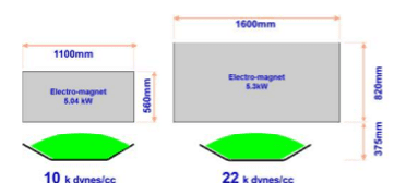
For example, and as demonstrated in the graph appended, two electromagnets of similar wattage of 5kW display dissimilar magnetic strength, and so because of the difference in their internal design. The smaller electro-magnet (on the right) has a force density of more than double the larger electromagnet (on the left).
The difference is due to the balance between the volumes of the wire. More turns on the coil require less current for the same ampere-turns and running temperatures. The cooler the running the less current is required; therefore, more turns are required for the same ampere-turns. Cooler running can be obtained either by forced cooling, such as circulating oil or air, increasing the surface area for heat dissipation or a combination of both. Therefore, ordering a 5 Kw magnet could result in a unit only half the strength required for the application or, alternatively, twice the strength required.
Gauss measurement is often perceived as the best performance measurement for a magnet. It is a misconception. Force density is the only accurate way to compare magnetic fields. Force density is the force per unit volume exerted on a ferrous object at any given distance from the face of the magnet and is expressed in Dynes in the metric system.
The Gauss and Gauss gradient are used to calculate the mechanical forces acting on an object. The Gauss unit (cgs system) denotes the number of magnetic lines of flux per square centimeter at a given point. For high intensity field, the unit used is the Tesla unit (Sl system) that is equal to 10,000 Gauss.
Force density is calculated using three gauss figures – one at the point we are considering ‘G’ and two equally spaced either side of this point ‘G1’ and ‘G2’. Ideally, the distance either side of ‘G’ should be half a centimeter apart. See diagram.
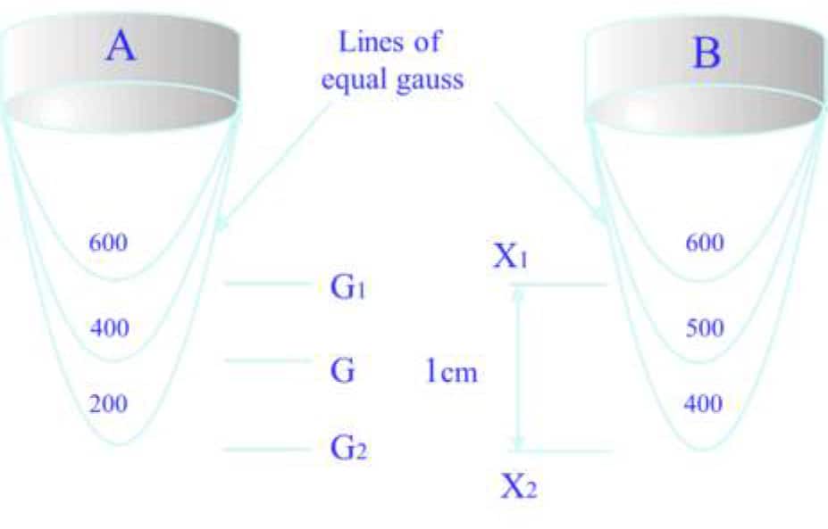
Here below is illustrated how the flux density of 400 gauss at distance ‘G’ for magnet ‘A’ has a greater attractive force than magnet ‘B’, even though the flux density at the same distance for magnet ‘B’ is a higher figure of 500 gauss. This is why the shape of the object is also important.Here below is illustrated how the flux density of 400 gauss at distance ‘G’ for magnet ‘A’ has a greater attractive force than magnet ‘B’, even though the flux density at the same distance for magnet ‘B’ is a higher figure of 500 gauss. This is why the shape of the object is also important.

While a dyne is a fixed mechanical force, being equal to the force needed to accelerate a mass of one gram at a rate of 1cm per second, it cannot be directly applied to the object being considered. The shape of an object has some bearing on the way flux is conducted, e.g., a long thin shape is a better bar magnet than a short fat one, therefore a compensating factor must be used.
Typical compensation factors
| Item | Factor |
| Bar with a shape ratio of 1×4 | 1.34 |
| Bar with a shape ratio of 1×3 | 1 |
| Hexagonal nut | 0.47 |
| Cube | 0.296 |
| Sphere (worst possible shape for magnetic attraction) | 0.23 |
To demonstrate how important shape is when considering a magnetic circuit to perform a particular task, here is an example on how to calculate the force acting on a 1cm cube when the force density is 44,000 dynes per cc.:
The force acting on the object equals the force density multiplied by the compensating factor for a cube multiplied by the volume of the object, all divided by the conversion from dynes to grams.

The weight of the cube (for example iron) is 7.8 grams and the calculated force on the cube is 13.29 grams. The force exceeds the weight and will easily lift the cube in air. Therefore, a force density of 44,000 dynes per cc will easily lift a 1cc block of iron in the air.
Performing the same calculation for a 1 x 4 iron bar of volume 1cc (weighing 7.8 grams) the force equates to a force of 60 grams. The bar has the same volume and weight as the cube but the force acting on it increases from 13.29g to 60g. It is important to remember that the effective position of the point of calculation for attractive force is at the center of the object.
The pull is proportional to the volume and weight of the object. This can be demonstrated using two steel spheres – one is 75mm dia., the other 15mm dia.

The distance from the surface of the magnet to the center of each of the spheres is identical. One weighs 1.8 kilos and the other only 16 grams. The force density is also identical but the force acting on the 75mm sphere is 125 times that of the 15mm sphere.
The minimum Force Density above which lift is achieved in air for a given shape is always the same.
In the USA, the magnetic field is measured using the Force Index. It has no units, but a mixture of cgs and imperial units (Gauss and Inches). To convert Force Index (in) to Force Density, divide Force Index by 2.54.
Can permanent magnets deteriorate over time?
This is no longer true thanks to the quality of the magnetic material used nowadays. Provided the material is used within its designed working conditions the magnet will not lose its strength, unless subject to excessive thermal or physical shocks. Permanent, therefore, means permanent. Variations will occur and are generally linked to the operating temperature but, within specified limits, the strength of the magnet will revert to the original level as the temperature returns to ambient. In addition, it is worth noting that poor quality worth noting that poor quality magnet materials will produce poor quality magnets.
In a bulk handling environment, this last misconception needs to be covered: a magnetic field can be insulated.
For example, placing a non-magnetic material on an iron surface, such as lagging an iron roller in a conveyor system with rubber, will not insulate the roller from a magnetic field to prevent it from becoming magnetically induced. The rubber will only act as a spacer. Only when the rubber is as thick as the depth of the field can it prevent the roller from being induced.
Prevention of magnetic field inducing an adjacent piece of ferrous equipment is possible through the deflection of the field or by absorbing it with suitable iron baffles. On site, in close proximity to magnets, it is usual to manufacture chutes and ducts in non-magnetic material rather than try to deflect the field. Deflecting a magnetic field can also adversely affect the operation of the magnetic circuit.
Conclusion
The truth is that magnets are not magic and for mostly commercial reasons, they will not eliminate 100% of the tramp iron that found its way in the primary material during its transportation. To guarantee 100%, the following factors need to be known:
The size and shape of the tramp iron
The iron content
The orientation under, over and through the magnet
The amount of tramp iron expected.
As no customer can provide this data accurately, a full 100% guarantee cannot be offered.
A combination of magnetics separators and metal detectors remains the most efficient way to protect expensive machinery and to ensure that the product quality is as good as can be.