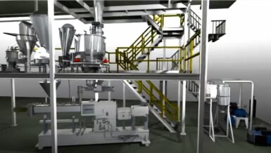

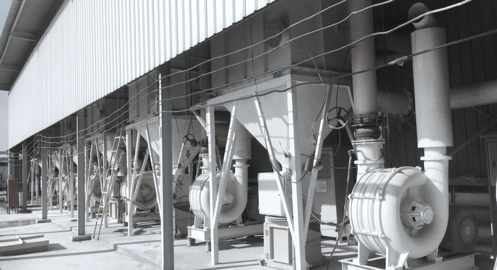
Amid this intricate network, a paramount yet often underestimated component is the dust collection system, meticulously stationed at the system’s terminus to purify the air used for material conveyance.
Undoubtedly, the ramifications of an undersized or improperly configured dust collector are far-reaching. Such oversights can usher in challenges, from undesirable dust emissions to differential pressure (DP) surges across the filtration media, necessitating frequent and costly cleaning cycles and culminating in a truncated media lifespan. These complications transcend specific applications, and the unique demands of pneumatic conveying compel a comprehensive approach to forestall not only these issues but also the specter of over-pressurization in terminal equipment – a potential catalyst for airborne dust escaping through equipment apertures, potentially undermining overall system performance.
Defining Dust Collection Equipment for Pneumatic Conveying Systems
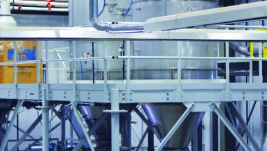
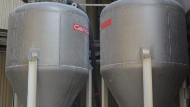
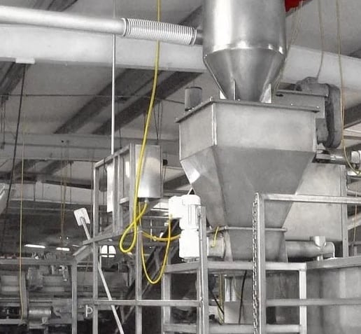
Within positive pressure conveying systems, filtration equipment configurations primarily consist of bin vent dust collectors strategically mounted on silos, hoppers, or process machinery. Additionally, filter receivers feature a hopper and various discharge mechanisms such as rotary valves, butterfly valves, or slide gates. In this context, the silo or associated equipment represents the terminus of the conveying system, while the hopper in a filter receiver assumes this role for the connected system.
The vacuum filter receiver is the terminal element most commonly encountered in the negative pressure (vacuum) conveying systems domain. This functional unit shares many similarities with its positive pressure counterpart but is meticulously designed to withstand the unique vacuum pressures inherent in the application.
The Art of Dust Collector Configuration
The intricacies of dust collector configurations are revealed when one looks at the quantified airflow, primarily defined by two critical parameters: the air-to-cloth ratio (ACFM per square foot of media) and interstitial velocity (FPM).
The air-to-cloth ratio measures “contaminated” air passing through the effective media cloth area. Optimal values hinge on a complex interplay of media design and the unique characteristics of the dust at hand. Essentially, this ratio encapsulates the velocity at which dust-laden air converges with the filtration media. In this context, filtration velocity (FPM) often becomes synonymous. It is vital to underscore that maintaining an appropriate filtration velocity is pivotal, as an excess can result in the entrapment of dust on the media’s surface, the penetration of dust deep into the media for retention, or even the escape of dust as emissions. Elevated differential pressure, arising from surface-retained or embedded dust, necessitates greater cleaning energy to rejuvenate the media, which may significantly reduce the media’s operational lifespan.
The concept of interstitial velocity captures the speed at which air and dust ascend through the media’s cross-section, and the optimal values are intricately linked to the terminal velocity of the dust particles. A surfeit of interstitial velocity can stifle the effective discharge of dust from the media, resulting in dust build-up beneath the tube sheet or among the media elements. This accumulation reduces the effective air permeability of the cloth, invariably increasing the filtration velocity. Moreover, the accrued dust can precipitously descend, potentially flooding connected vessels and causing harm to the filter media, including dislodging elements in a bottom-load collector. In select applications, it is vital to scrutinize the “can” velocity within a dust collector – the velocity in the filter housing below the filter media – to prevent issues stemming from excessive values.
Typically, the “can velocity” region outpaces the interstitial velocity area, making it a non-issue in collector sizing. However, when a converging transition to a smaller opening on the connected vessel is at play, the velocity in the smaller opening merits careful consideration to prevent dust from escaping.
Determining the Right System Airflow
In vacuum conveying systems, configuring the collector hinges on the airflow at the air mover’s inlet (ICFM).
In positive pressure conveying systems, calculating the applicable airflow depends on the particular conveying regimen. In dilute-phase conveying applications, typically facilitated by a rotary valve, the relevant airflow aligns with the SCFM of the blower, augmented by a slight surge factor to accommodate potential pressure surges due to material fluctuations.
For semi-dense and dense phase conveying, where pressure vessels discharge materials into the conveying line, the surge factor assumes a more substantial magnitude. The rapid pressure drop when a vessel empties creates a momentary surge of airflow that can overwhelm a collector if not correctly configured.
Conclusion
Precisely tailoring the size and configuration of a dust collector for pneumatic conveying applications necessitates an intimate understanding of the system’s operational dynamics, the unique attributes of the dust, and the array of available media configurations.
When executed precisely, a well-designed dust collector within a pneumatic conveying system guarantees consistent performance and extends the filtration media’s longevity, promoting operational efficiency and cost-effectiveness.