

Advantages over L.I.W.:
- Uninterrupted dosing process, which also means:
- 1 feeder instead of 2 in series needed for each dosing position
- This can reduce the volume of a CM machine at least by 4 times
- No flexible connections • Less sensitive to vibrations
- No dead corners where powder can accumulate, i.e.:
- Cleaning without disassembly becomes possible.
- Basically, a low-cost concept.
- Well-defined operating parameters (speeds, inertia…) that allow optimisation by Discrete Element Modelling or similar simulations
Current drawbacks:
- Prototypes in 3D printed PLA limit tests with poorly flowing powders
- Brand-new concept that makes sense, but there is still a way to go to get an industrial product.
- We do not have an industrial environment to develop this further.
First prototype (2022)
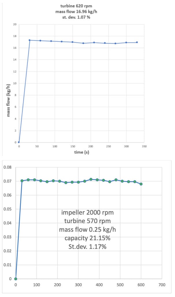
- Built to prove all claims in the patent. • Initial tests gave an idea of range and accuracy. (see fig. 4)
- Added features (claims 6-14) gave it a complex, expensive appearance and made it unsuitable for testing with poorly flowing powders
Second prototype (2023)
- Shows the core of the concept with only the necessary parts
- Built to test the concept (claims 1 – 4) with powders that flow poorly
- Catch-scale test (continuous mass flow measurement) proving the influence of PID control on the mass flow stability.
- More accurate understanding of process sensitivities and failures
Updated description of the process:
- The rotating impeller (or distribution wheel) throws whatever it gets against the turbine.
- The response (speed, deflecting angle, torque) of the turbine is proportional to what it receives from the impeller.
- In an airtight system, the turbine reacts only when powder is added
- The sensitivity of the turbine’s response is dramatically increased by adding powder only when the turbine is already in a stationary dynamic (rotating, deflecting…) state, i.e. in the presence of a constant air or gas flow initiating the turbine.
- To optimize this, powder, and air (or gas) should each be fed through a separate channel, where:
- The air inlet is best equipped with a flow controller that continuously provides the constant air flow rate that was required to get the turbine into the dynamic state
- The powder duct is airtight so that no uncontrolled air leaks can occur there, causing turbine malfunction.
- Good flowing powder can be dosed by means of a dosing disc centrally located in the impeller as described in the patent. (fig.3)
- Poorly flowing powders require a different approach, for example:
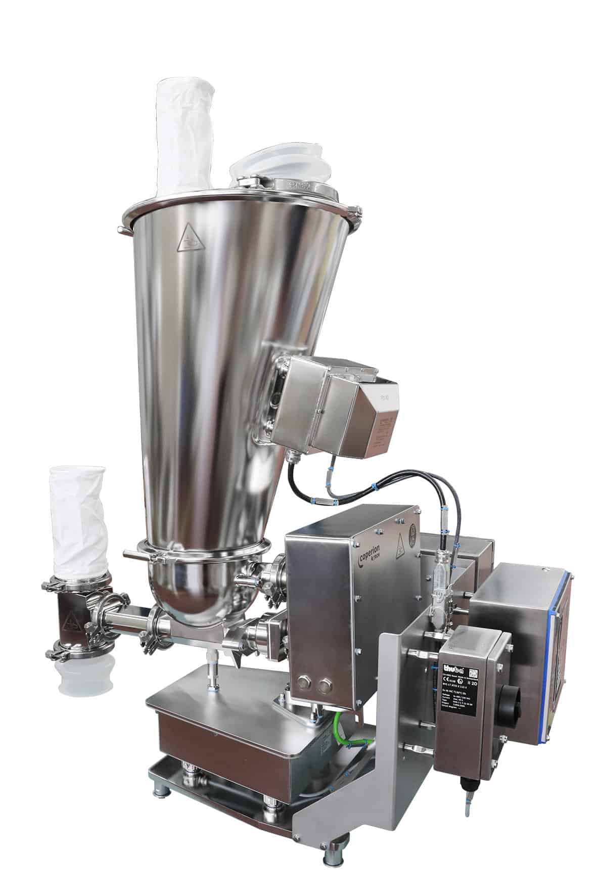
- A twin screw that drops the powder centrally into the impeller (e.g. fig.1)
- A thin rotating conical helix (e.g. a vertical leaf spring strip that is not able to support a bridging powder mass) in a hopper above the impeller can do the dosing job. (fig.2)
- ….
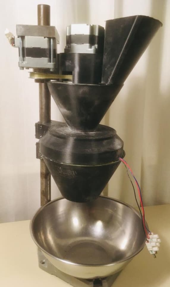
Fig.1 Turbine feeder with twin screw
The twin screw should be as close as possible to the impeller to get a fast response.
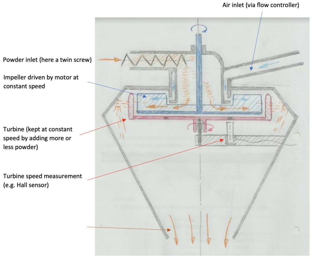
Fig.2 Turbine feeder with 1 (or more) conical helix(es)
For poorly flowing powders with strong bridging effects. The slope of the hopper and helix can be optimised. The aim is that the powder is always supported by the hopper wall and thus does not rotate on or with the helix. Ratholes may occur, but they should not cause air leaks.
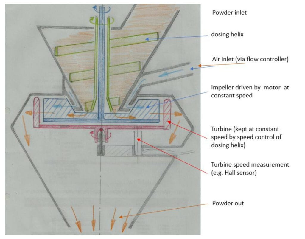
Fig.3 Turbine feeder with dosing wheel (wheel with or without ribs)
Works great for well-flowing powders. Fast response. Keep in mind the angle of repose of the powder to avoid losing powder when the dosing wheel is not turning.
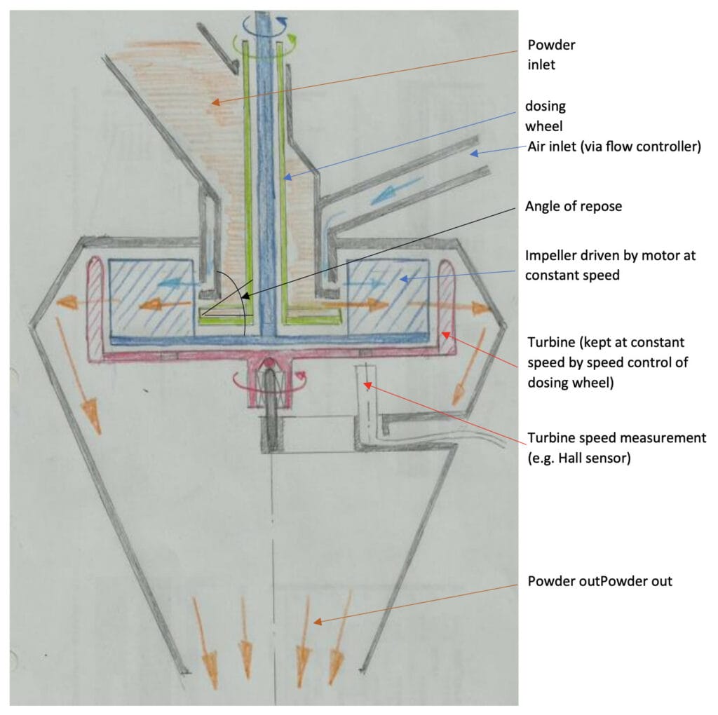
Fig 4: Test results prototype 1
Patent: WO2023042020A1 DOSING DEVICE
https://worldwide.espacenet.com/patent/search?q=pn%3DWO2023042020A1
Contact: solidsflow2022@gmail.com
Application: continuous manufacturing of food, pharma powders