

Potential Risks
Ignition source risks in operating a bucket elevator include:
• Sparks or Embers. Hot material from upstream can be introduced into an elevator and become an ignition source.
• Belt Slippage. Choking or plugging of inlet or outlet chutes which may cause belt slippage at the driven pulley and potential ignition from friction.
• Equipment Failures Buckets, bolts or other fasteners can fail and cause misalignment of the belt resulting in friction with the belt and housing or buckets to impact with the housing causing ignition.
• Bearing failure can cause overheating and provide a potential ignition. Dust dispersion takes place as material enters the boot area and again in the head area where material is thrown into the discharge chute area. This provides the fuel and dispersion requirements for a combustible dust explosion. The housing of the elevator leg offers a confined enclosure in which an initial explosion may take place.
Challenges
• Isolating external ignition sources from entering the elevator.
• Controlling dust cloud formation within the elevator housing by dust control.
• Distribution of the motion of the belt & buckets during operation moves air along with product and creates a low efficiency fan effect.
Boss Products’ Solutions

Explosion Prevention
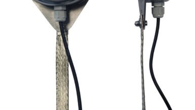
• Prevent ignition sources such as sparks or embers coming from upstream equipment from entering the elevator by use of spark detection/extinguishing (Raptor Spark), thermal probes, etc.
• Properly designed dust collection in the head and boot section to limit the concentration of combustible dust during operation.
• Monitoring systems (M-Jet) for bearing temperature, belt alignment, chute plugging and belt slippage can prevent ignition sources caused by equipment malfunction.
Explosion Prevention Active Protection
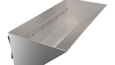
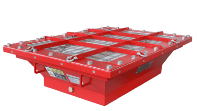
• Explosion vents as prescribed by NFPA 660 (EVVL) in the leg housing and head section (or flameless explosion vents (EV-VI) if the leg is located indoor)
• Exhaust duct isolation with Vigiflap preventing propagation from dust collector.
• Spark detection/extinguishing in plenum of hammer mills feeding into elevator legs
• Explosion isolation rotary valve in hammer mill plenum discharge feeding to elevator leg
Explosion Mitigation Passive Protection
• Raptor X sensors located in the boot and head sections
• Raptor X isolation cannisters in the inlet and outlet chutes, up and down leg housings (boot and head areas) exhaust ducting
• Suppression cannisters located in the boot and head sections
Additional Protection
• Explosion isolation valve VF on airlift inlet duct & airlift pipe (depending on product and
loading) & filter receiver clean air ducting if returning air
• Spark detection/extinguishing on airlift pipe
• Explosion venting on filter receiver
• Explosion isolation rotary valves in filter receiver hopper discharge