The design process for silos, bins, and hoppers is often thought of as a “black art,” known by only a chosen few. However, a proven, practical method for storage bin process design has been in use for over 60 years. Just as a pump must be designed specifically for the liquid it will handle, so, too, must a silo be designed for a particular powder or bulk solid. The characteristics of the material being handled will dictate the storage vessel design.
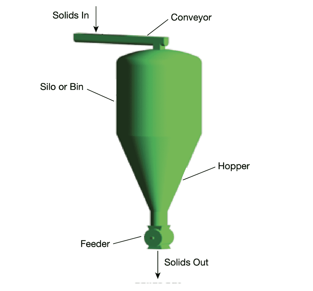
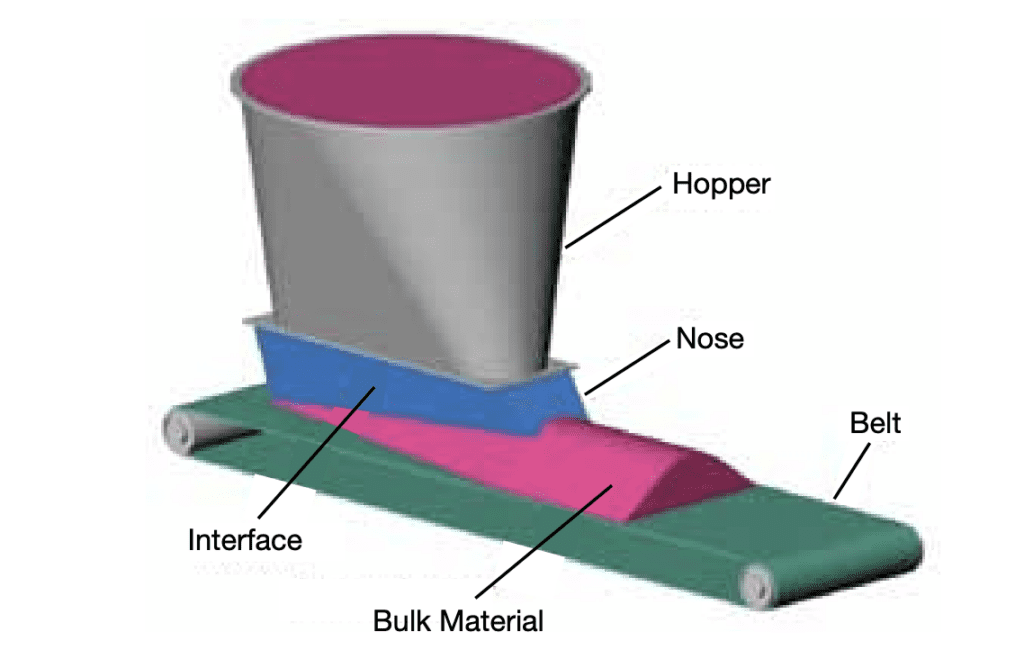
Although design requirements such as storage capacity, throughput, overall height, and other spatial features are important inputs, other critical parameters, including powder cohesion, coefficient of sliding friction, and permeability, can significantly affect the bin’s design. Figure 1 illustrates a typical bin installation. A conveyor delivers the bulk material to the bin, which provides storage capacity within the flow path; a feeder (a rotary valve in this case) controls the solids discharge from the bin and feeds the material to the next part of the process. In any industrial application, negative consequences may arise if the bin does not reliably discharge the powder or bulk solids to the downstream process or if the discharging material no longer meets quality specifications.
This article details a step-by-step process to design bins that will ensure reliable discharge of powders and bulk solids based on their unique flow behaviors and the requirements of the process. The terms bin and silo are used interchangeably throughout the article.
Step 1. Define the storage requirements
The first step in designing a bin to store a powder or bulk solid is to review key storage requirements and operating conditions. These include:
- Storage capacity. How much material (e.g., pounds, tons, cubic feet or meters, truck load, railcar) must be stored? Is one bin sufficient or are multiple bins required? Where will the bin be located (e.g., indoors, outdoors)?
- Discharge frequency and rate. How long will the bulk solid remain in the bin without movement? What are the maximum, minimum, average, and instantaneous discharge rates? Is the rate based on weight (mass) or volume? What is the required feed accuracy?
- Temperature and pressure. Is the material at a higher or lower temperature than the surrounding environment? Is the material being fed into a positive- or negative-pressure environment (e.g. reactor, pneumatic conveying line)?
- Fabrication materials. Is the bulk solid corrosive or abrasive (e.g., alumina, iron ore)? Are corrosion-resistant alloys needed? Are ultrahigh-molecular-weight (UHMW) plastic liners acceptable? Is the application subject to any regulatory compliance requirements (e.g., U.S. Food and Drug Administration)?
- Safety and environmental considerations. Are there material explosibility concerns, maximum dust exposure limits, or other safety or environmental issues?
- Bulk solid uniformity. What is the required material uniformity (e.g., particle size, shape, potency, moisture content, color)? Is particle segregation likely with your material? If so, how will segregation affect production and the final product?
Step 2: Understand bulk-solids flow problems
While bulk-material handling problems can be experienced in a variety of equipment (e.g., feeders, transfer chutes, dust collectors), they most often occur in bins. Common flow problems include:
- Arching or bridging. A no-flow condition in which material forms a stable arch (bridge, dome) across the outlet of a bin (Figure 2)
- Ratholing. A no-flow condition in which material forms a stable open channel within the bin (Figure 3), resulting in erratic flow to the downstream process
- Flooding or flushing. A condition in which an aerated bulk solid behaves like a fluid and flows uncontrollably through an outlet or feeder
- Flowrate limitation. An insufficient flowrate, typically caused by counter-flowing air slowing the gravity discharge of a fine powder
- Particle segregation. Separation of particles by size, shape, density, etc.; segregation may prevent a chemical reaction, cause out-of-spec product, or require costly rework.
There are many consequences of flow problems. A bin experiencing ratholing will have limited live (i.e., useable) capacity, as low as only 10–20% of the bin’s rated storage capacity. Additionally, material stagnation in a poorly designed bin can lead to caking of materials, spoilage of food powders, or other forms of quality degradation. Collapsing arches, ratholes, and nonuniform loading contribute to localized, and at times catastrophic, storage vessel failures.
Many of these flow problems occur in a bin that is discharging material in an undesirable flow pattern. The discussion of Step 5, choosing the type of flow pattern in the bin, explains how the flow pattern can directly influence the type of material flow performance you will experience.
Step 3. Measure the flow properties of the bulk solid
The flow properties of the material must be measured in order to predict and control how it will behave in a bin. These flow properties can be measured1,2 in a bulk-solids testing laboratory under conditions that accurately simulate how the material is handled or processed in your facility. If the bulk solid’s properties change rapidly or if special precautions are required, tests should be conducted onsite. Table 1 lists the most important bulk-solids handling properties that are relevant to predicting flow behavior in bins and hoppers. Each of these parameters can vary with changes in:
- moisture content
- particle size, shape, and hardness
- temperature
- storage time at rest
- chemical additives
- pressure
- wall surface
Step 4. Calculate the approximate size of the bin
The approximate height of the cylinder section needed to store the desired capacity (initially ignoring the capacity in the hopper section) is simply:
where:
- H is the cylinder height (m)
- m is the mass to be stored (kg)
- ρavg is the average bulk density (kg/m3)
- A is the cross-sectional area of the cylinder section (m2)
The final cylinder height needed to hold the required volume depends on the volume lost at the top of the cylinder due to the bulk solid’s angle of repose, as well as the volume of material in the hopper section. Because this design process is iterative, a reasonable estimate for cylinder height is sufficient at this point.
Try to keep the height of a circular or square cylinder between about one and four times the cylinder’s diameter or width. Values outside this range often result in designs that are uneconomical.
Note that the bin’s calculated storage volume and its live, usable volume are not necessarily identical. Depending on the type of flow pattern in the bin (described in the next section), stagnant regions of material in a bin will reduce the usable capacity.
| Parameter | Measured By | Required To |
|---|---|---|
| Cohesive strength | Direct shear tester | Calculate outlet size to prevent arching and ratholing |
| Wall friction | Direct shear tester | Calculate hopper angles for mass flow, internal friction |
| Bulk density/compressibility | Compressibility tester | Calculate pressures, bin loads; design feeder |
| Permeability | Permeability tester | Calculate discharge rates, settling time |
| Segregation tendency | Segregation tester | Predict whether or not segregation will occur |
| Abrasiveness | Abrasive wear tester | Predict the wear life of a bin liner |
| Sliding at impact points | Chute tester | Determine minimum angle of chute at impact points |
| Particle friability | Annular shear tester | Determine effect of flow pattern on particle breakage |
Without this information, bin geometry may be chosen based on guesswork
Step 5. Determine the type of flow pattern needed
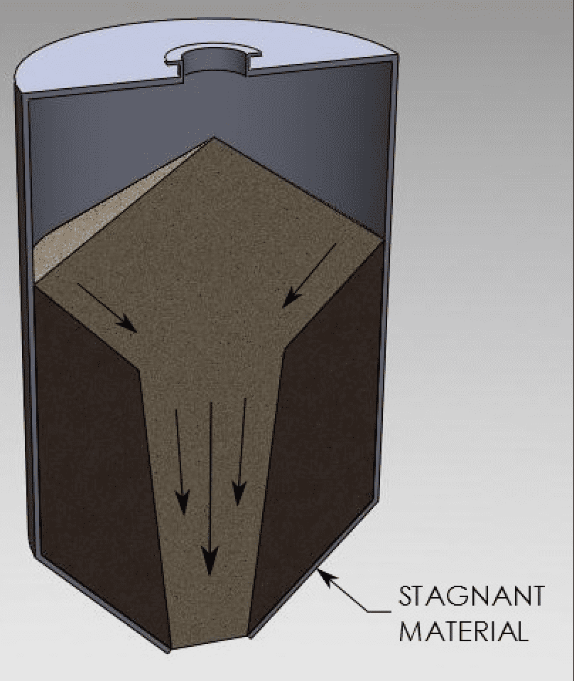
Although it is natural to assume that a bulk solid will flow through a storage bin in a first-in/first out sequence (just as liquid moves through a tank), this typically is not the case. Many bins discharge bulk solids in a funnel-flow pattern.
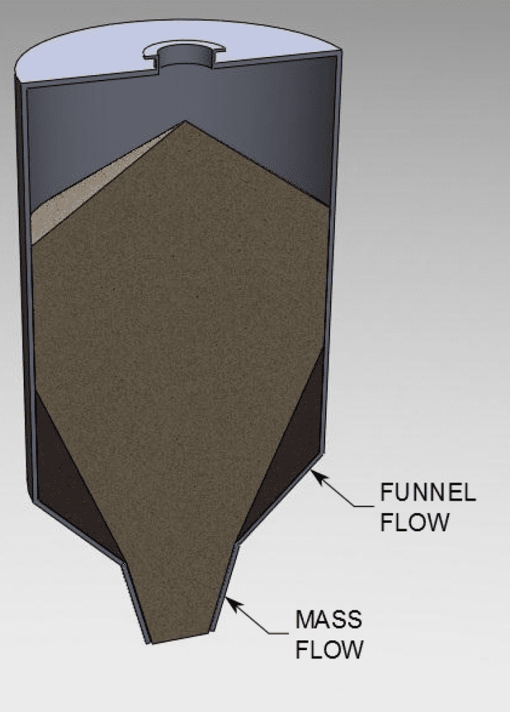
With funnel flow, some of the material moves in the center of the hopper while the rest remains stationary along the hopper walls (Figure 4). This first-in/last-out sequence is acceptable if the bulk solid is relatively coarse, free-flowing, and non-degradable, and if segregation during silo discharge is not an issue. Provided that the bulk material meets all four of these criteria, a funnel-flow bin may be the most economical storage choice.
Unfortunately, with many bulk materials, funnel flow can create serious product quality and process reliability problems. Arches and ratholes may form, and flow may be erratic. Fluidized powders often have no chance to deaerate, so they remain fluidized in the flow channel and flood when exiting the bin. Some materials cake, segregate, or spoil. In extreme cases, unexpected structural loading results in equipment failure.
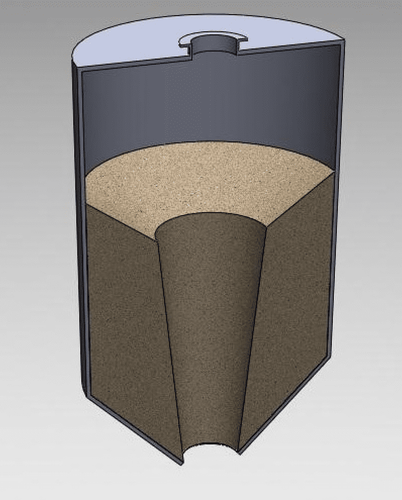
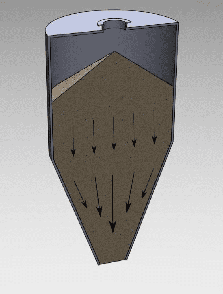
These problems can be prevented by designing storage vessels to move materials in a mass flow pattern. With mass flow, all the material moves whenever any is withdrawn (Figure 5). Flow is uniform and reliable; feed density is independent of the head of solids in the bin; there are no stagnant regions, so material will not cake or spoil, and level indicators work reliably; sifting segregation of the discharge stream is minimized by a first-in/first-out flow sequence; and residence time is uniform, so fine powders deaerate. Mass-flow bins are suitable for cohesive materials, powders, materials that degrade with time, and whenever sifting segregation must be minimized.
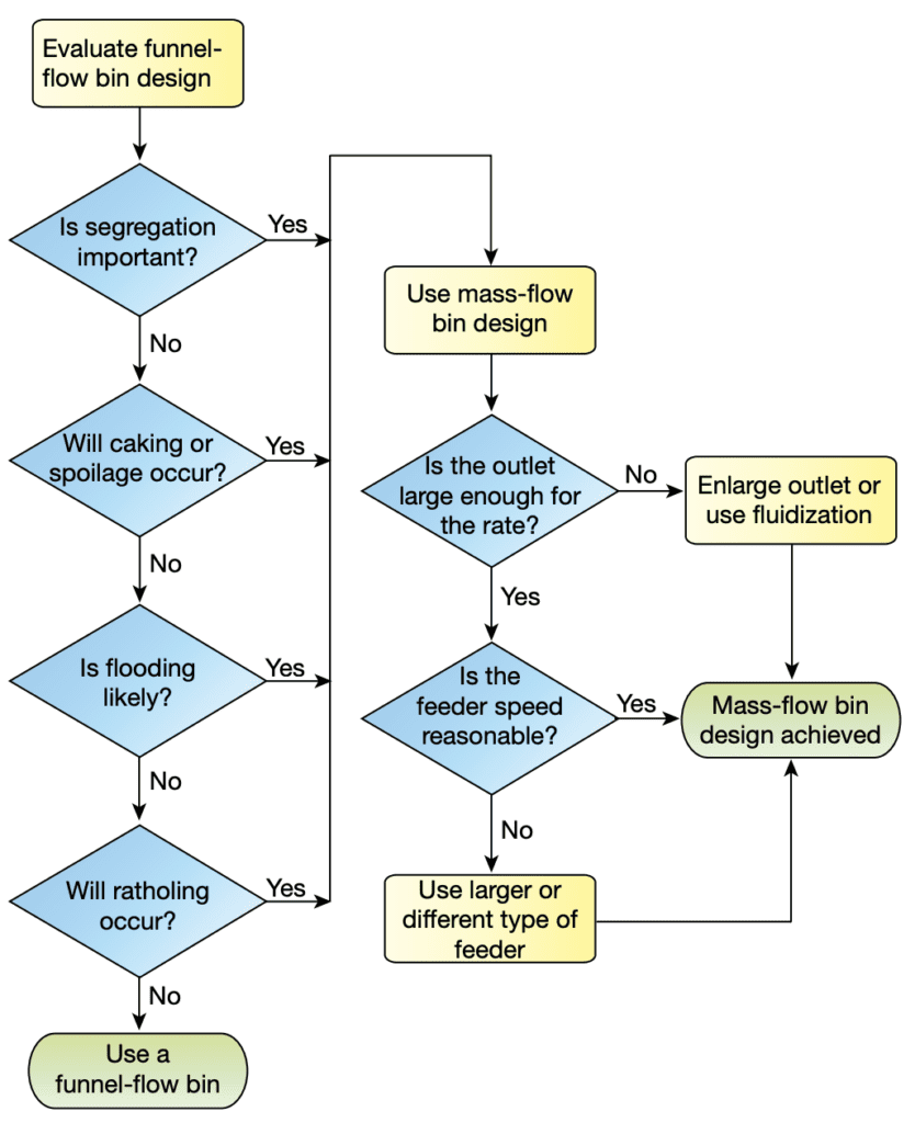
Use the flowchart in Figure 6 and the requirements identified in Step 1 to determine which flow pattern your bin needs. As indicated in the diagram, if segregation, caking, spoilage, flooding, or ratholing are likely to occur, then a mass-flow discharge pattern should be selected. If a mass-flow bin is required based on the flow characteristics of the powder or bulk solids, the next step is to determine an appropriate outlet size and feeder. Keep in mind that the mass-flow bin design process is iterative. The actual outlet size will depend on the required discharge rate from the bin and the feeder selected. These factors, in turn, affect the slope and shape of the mass-flow hopper wall, as discussed in the next section.
Step 6. Define the hopper geometry based on the chosen flow pattern
Designing for mass flow. With this flow pattern, it is essential that the converging hopper section is steep enough and the wall-surface friction low enough to facilitate solids flow without stagnant regions whenever any solids are withdrawn. In addition, the outlet must be large enough to prevent arching and achieve the required discharge rate.
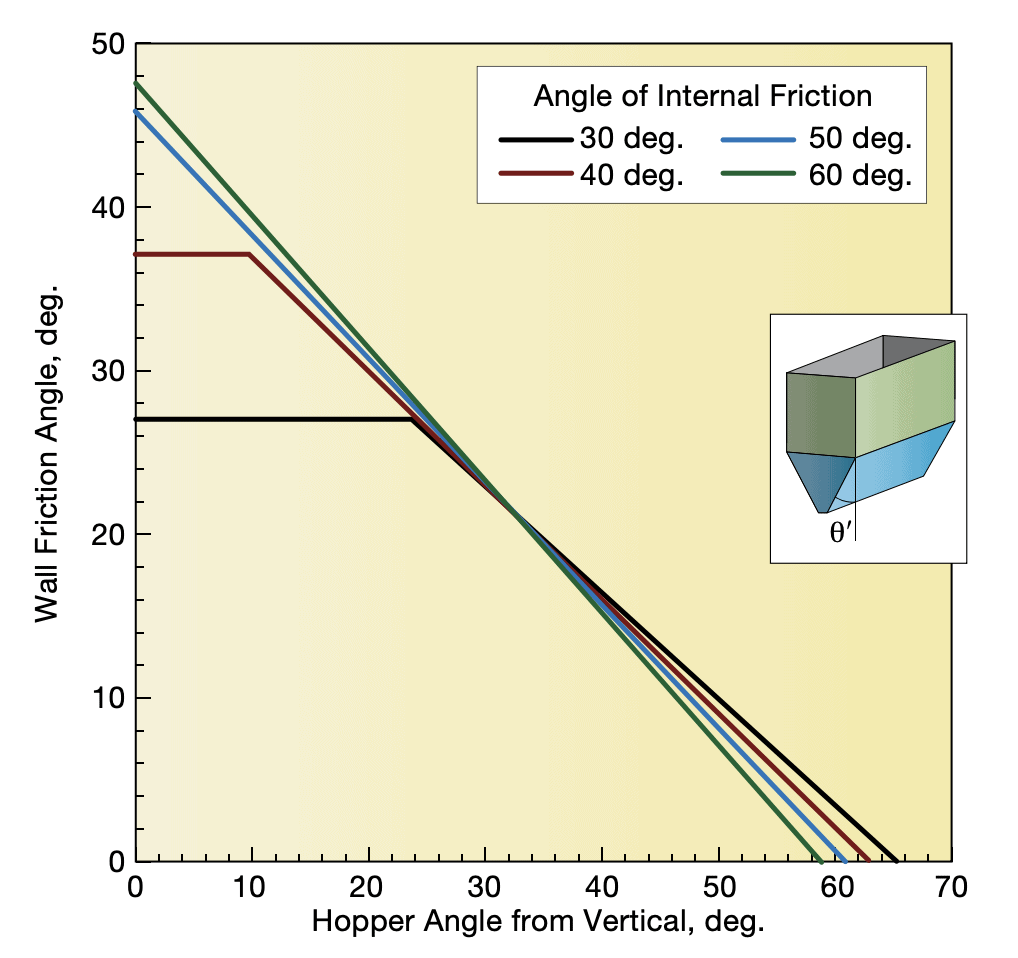
Andrew Jenike, renown as the founding father in the field of bulk solids handling, developed hopper design charts showing the limits of mass flow for conical and wedge-shaped hoppers1. In these charts, the hopper angle (measured from vertical) is on the abscissa, and wall friction angle is on the ordinate, as shown in Figure 7 for conical hoppers and Figure 8 for wedge-shaped hoppers. The wall friction angle is determined through powder testing with various wall surfaces, such as carbon steel, stainless steel, plastic, abrasion-resistant liners, etc. The coefficient of sliding friction for the powder against a wall surface can be calculated from the tangent of the wall friction angle. Tests are conducted using a direct shear tester according to ASTM standard test method D-61282.
Depending on the combination of hopper angle and wall friction angle, either mass-flow or funnel-flow discharge with the particular bulk material will result. Simply speaking, a highly frictional bulk solid, such as sand, will require a steep hopper angle to achieve mass flow, whereas a low-friction bulk solid, such as smooth catalyst beads, can achieve mass flow at a relatively shallow hopper angle.
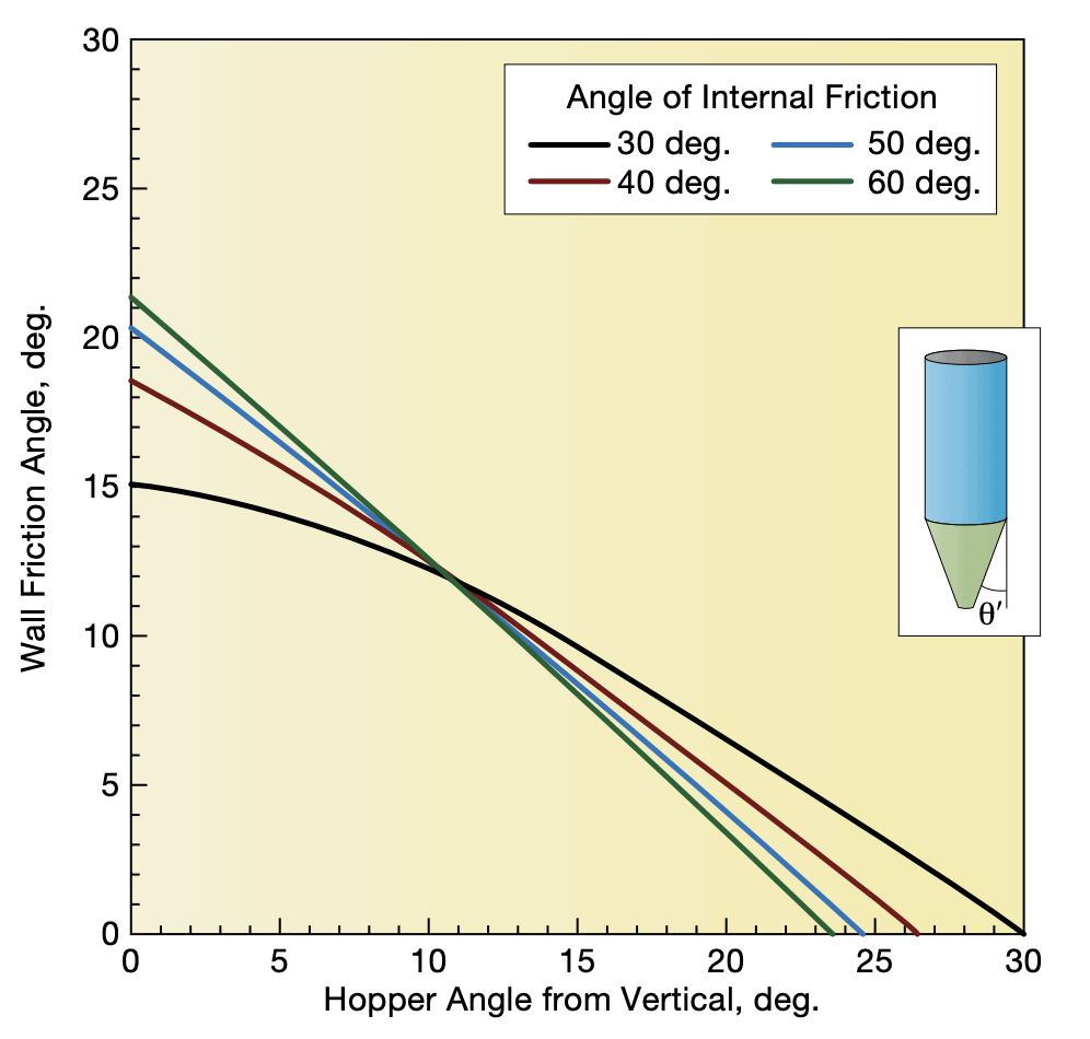
Note that a 60-deg. (from horizontal) hopper angle for a cone is usually not sufficient to provide mass flow for most bulk solids. This angle is optimum for manufacturing the hopper with minimal waste — it will not guarantee mass flow as is sometimes promised.
Calculating the outlet size needed to overcome arching is more challenging. Arching can be analyzed by measuring the cohesive strength of the material. First, the flow function of the material (i.e., the cohesive strength vs. consolidating pressure) is measured through laboratory testing. This test is also conducted according to ASTM D-6128 using a direct shear tester2. As in the wall friction test, consolidating forces are applied to material in a test cell, and the force required to shear the material is measured. This information directly relates to a material’s ability to form a cohesive arch or a rathole. Once the flow function is determined, minimum outlet sizes required to prevent arching can be calculated using the design charts published by Jenike1. Reference 3 provides the step-by-step Jenike method for hopper outlet calculation based on a material’s cohesive strength.
Sizing the outlet for the required discharge rate is straightforward, provided the bulk material is both coarse and free-flowing4. A material is considered coarse if the majority of its particles are larger than 1/8 in. or 3 mm. A free-flowing material is one that does not experience arching or ratholing flow problems. Assuming that the bulk material is both coarse and free-flowing, such as plastic pellets, the following equation can be used to approximate the maximum discharge rate from a converging hopper:
where:
- M is the mass flowrate (kg/s),
- ⍴ is the bulk density (kg/m3),
- A is the outlet area (m2)
- g is acceleration (m/s2),
- B is the outlet size (m),
- ⍬ is the mass-flow hopper angle measured from vertical (deg.)
Equation 2 will not accurately estimate the flowrate of a fine powder (e.g., fumed silica, terephthalic acid). Because it does not account for the material’s resistance to airflow (or permeability), it will grossly overestimate the hopper’s discharge flowrate capability. A more accurate estimation of powder discharge rate can be made using the powder’s permeability5,6, but the analysis is complex and beyond the scope of this article.
Designing for funnel flow. The key requirements for funnel flow are sizing the hopper outlet large enough to overcome arching and ratholing, and making the hopper slope steep enough to be self-cleaning.
Determining the minimum dimensions to overcome arching and ratholing requires knowledge of the material’s cohesive strength and internal friction. References 1 and 3 provide the relevant design procedures. It is important to note that with funnel-flow bins, overall size matters, whereas the design of mass-flow bins is essentially independent of scale. Ratholing is affected by consolidating pressure; thus, large funnel-flow bins have a higher ratholing tendency. In mass flow, there is no chance of ratholing, so the size of the bin is not important.
The requirement that the funnel-flow bin be capable of self-cleaning can usually be met by making the hopper slope 15 deg. to 20 deg. steeper than the wall friction angle. This assumes that a stable rathole has not formed.
Step 7. Develop the overall bin geometry
A square or rectangular straight-sided section at the top of a bin is preferable to a circular cross-section, because it is easier to fabricate and it provides a larger cross-sectional area per unit of height. However, material flow or structural issues often outweigh these advantages. Flat walls are susceptible to bending, whereas a cylinder is able to resist internal pressure through hoop tension. Therefore, thinner walls and less external reinforcement are needed for circular cross-sections. In addition, there are no corners in which material can build up, which is particularly important at the interface between the bin and the hopper.
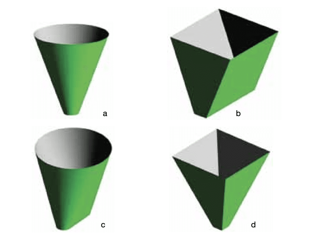
Hoppers come in a variety of geometries. Figure 9 shows some of the more common hopper shapes. When choosing a hopper, consider these factors:
- Headroom. Typically, a wedge-shaped hopper (Figures 9b and 9c) can be 10 deg. to 12 deg. less steep than a conical hopper and still promote mass flow. This can translate into significant savings because of the lower hopper height, which is important when retrofitting existing equipment in an area with limited headroom.
- Outlet sizes. To overcome a cohesive or interlocking arch, a conical hopper needs to have an outlet diameter that is roughly twice the outlet width of a wedge-shaped hopper (provided the outlet length is at least three times its width). Thus, cones generally require larger feeders.
- Discharge rates. Because a slotted outlet typically has a larger cross-sectional area than a circular outlet, the maximum flowrate from a wedge-shaped hopper will be larger than that of a conical hopper.
- Sharp vs. rounded corners. Pyramidal hoppers (Figure 9d) usually cause a funnel-flow pattern to develop because of their in-flowing valleys, which are less steep than the adjacent side walls. Conical and transition hoppers do not have corners, which tend to allow material buildup.
- Capital cost. Each application must be looked at individually. While a wedge-shaped hopper requires less headroom and can use a less-expensive liner than a cone, the feeder and gate valve (if necessary) may be more expensive.
Step 8. Select the outlet feeder
The feeder is just as important as the hopper above it. To be effective, the feeder must uniformly draw material through the entire cross-section of the bin’s discharge outlet7. An obstructed outlet, due, for example, to a poorly designed feeder or partially opened gate, will result in funnel flow regardless of the hopper design.
Three common types of bulk solids feeders, along with key features required to ensure uniform withdrawal of material from the entire outlet of the hopper, are discussed in the following paragraphs.
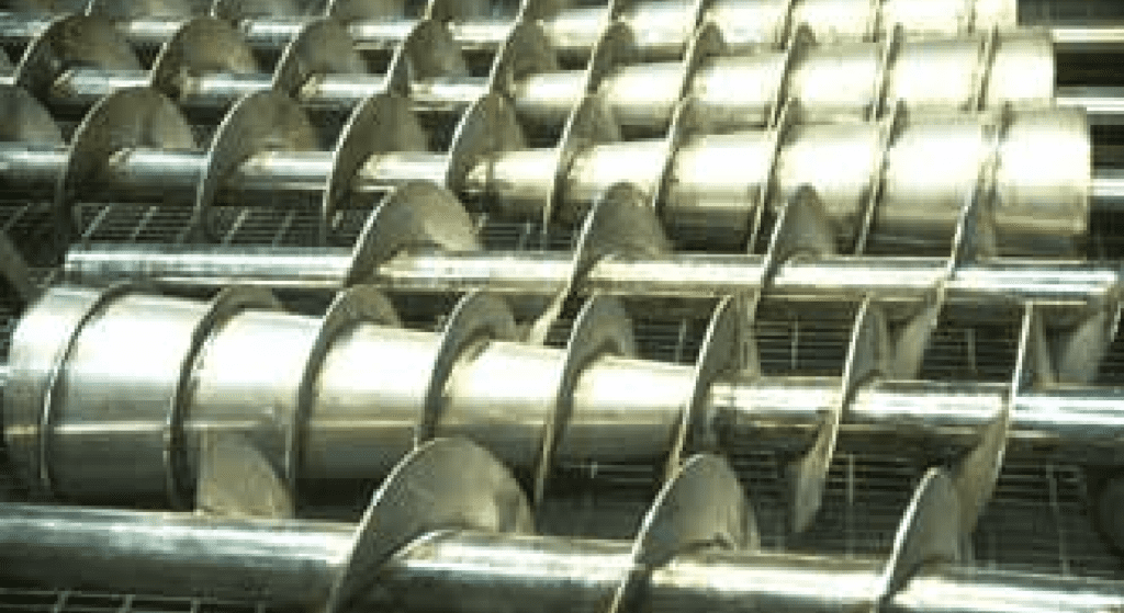
Screw feeders. These are well suited for use with hoppers that have elongated outlets. Since a screw feeder is totally enclosed, it is good for use with fine, dusty materials. In addition, it has few moving parts, so it requires less maintenance than a belt feeder.
The key to a proper screw-feeder design is to provide an increase in capacity in the direction of feed. This is critical when the screw is used under a hopper with a slot-shaped outlet. One common way to accomplish this is by using a mass-flow screw feeder design as shown in Figure 108. Each of the screws shown in this figure has a decreasing diameter (tapered) conical shaft followed by a section of increasing pitch.
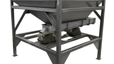
Belt feeders. Like screws, belt feeders can be a good choice for an elongated hopper outlet. Belt feeders are useful for handling cohesive or coarse bulk solids that require a high discharge rate. Since the idlers of a belt feeder can be mounted on load cells, a belt feeder can also be used to weigh the solids being fed (i.e., gravimetric operation).
Belt feeders are not as good as screws and rotary valves for handling fine or dusty materials. Therefore, if your plant is handling combustible or toxic dusts, belt feeders are not recommended, unless the entire feeder is enclosed, sealed, and incorporates proper dust collection measures.
The key to a proper belt-feeder design is to provide increasing capacity along the direction of feed. An effective way to increase capacity is to install a belt-feeder interface (Figure 11). Rotary valves.
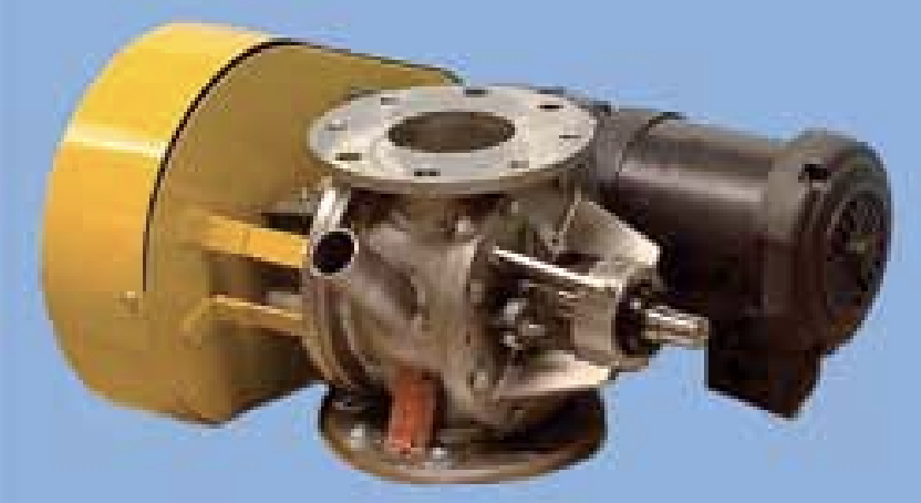
Rotary valves (Figure 12) are a common feeder, especially for discharging bulk materials into a pneumatic conveying system. The use of rotary valves is generally limited to hoppers with circular or square outlets. They should not be used for handling highly cohesive solids, because such materials have a high propensity for bridging that requires large hopper outlets.
A properly designed interface must be provided above the rotary valve to ensure that solids are withdrawn uniformly across the entire hopper outlet cross-section. Typically, a short vertical section, with a height of about 1 to 2 outlet diameters, should be placed between the hopper outlet and rotary valve inlet, as shown in Figure 1. Without such an interface, a preferential flow channel develops on the side of the hopper outlet where the solids are first exposed to the empty pockets, which results in nonuniform discharge. Material then stagnates over the remaining portion of the hopper outlet, thereby increasing the tendency for bridging and other flow problems.
Shallow sloping internal walls located at the inlet of many rotary valves can reduce the active hopper opening, causing material to remain stagnant and obstructing the solids discharge from the hopper above, as well as upsetting the mass flow in the hopper.
Step 9. Select the other functional components
Bin design also involves making decisions about other system components, including:
- Outlet gate or shut-off valve. In general, a slide gate at the bin outlet should only be used for maintenance purposes, not to modulate the solids flowrate. Therefore, it should be operated only in the full-open or full-closed position.
- Number of outlets. Although a multi-outlet hopper may be attractive for production flexibility, its design can have negative consequences structurally and from a flow perspective. This also applies to hoppers that have asymmetric geometries (e.g., one sloping wall, one vertical wall).
- Bin vent or dust collector. Depending on the method of vessel filling, an air-solids separator may be required conservation vent. A dual-acting conservation vent is typically installed on thin-shelled steel tanks to avoid excessive pressure and vacuum conditions and prevent damage.
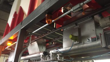
- Level detectors. There are two different types of level detection: point level detection and continuous level detection. Point level detectors are typically attached to the side wall or roof of a bin, and measure solids by direct contact using capacitance sensors, pressure diaphragms, or other means of proximity sensing. Common point level detectors include rotary paddles, tilt switches, and vibrating rods. Continuous level detectors usually consist of a roof-mounted device that emits radar or ultrasonic signals. The signals project down to the surface of the bulk material, and then rebound to a receiver for processing. Ultrasonic, guided-wave radar, or plumb-bob (i.e., yo-yo) detectors are commonly used to provide continuous detection of the top surface of the bulk material.
- Explosion protection. Depending on the explosivity characteristics of the powder, explosion vents, isolation, suppression, or inerting may be required. Numerous explosionprotection equipment and consulting firms are available to provide testing and expertise. Reference 9 explains how to limit dust explosion hazards and Ref. 10 outlines test procedures for determining explosivity.
- Access doors, manways, and poke holes. Poke holes (nozzle ports on the hopper walls) are not recommended in mass-flow hoppers, as they have a tendency to prevent flow along the walls, creating a problem that mass-flow bins are intended to solve. Access doors are also a frequent cause of problems; if they are essential, it is better to locate them in the cylinder rather than in the hopper.
- Ladders, railings, and platforms. Although these seem like minor details, depending on the need to access the vessel roof for maintenance, they may become important.
Step 10. Choose the material of construction
Storage bins and silos for handling powders and bulk solids come in a variety of materials, although they are typically constructed from metal or reinforced concrete.
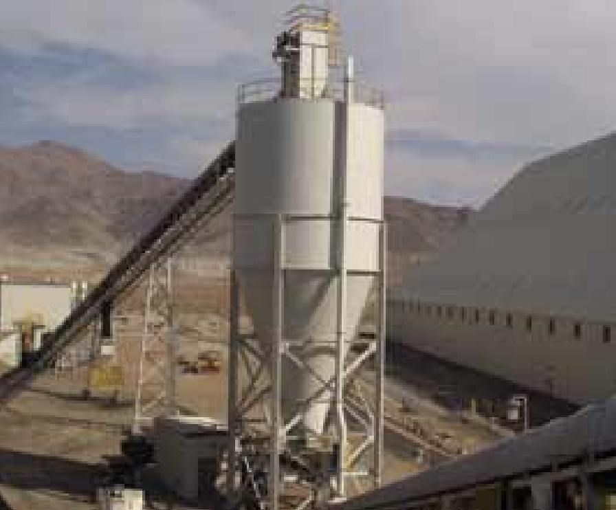
- Metal silos. Metal silos (Figure 13) can be made from carbon steel, stainless steel, or aluminum. They can be skirtsupported down to a concrete pad, or they can have simple leg supports. They can have panels that are seam-welded, bolted, or flanged, or use a hybrid construction. Metal silos have several advantages over concrete silos:
- Flexible fabrication. Metal silos can be shop-fabricated, field-fabricated, or made with a hybrid construction, where the vessel is started in the shop and is finished in the field.
- Sanitary construction. Stainless steel tanks are commonly used for pharmaceutical and food applications that require full sealing, cleanability, and corrosion resistance. Welded construction is preferred to bolted/gasketed construction to meet sanitary requirements.
- Wide variety of materials. In some cases, alloys such as Hastelloy or Inconel, or metals such as titanium have been used for silo construction. Fiberglass tanks can also be used
- Construction flexibility. Local weather conditions, such as freezing temperatures, may preclude the construction of concrete silos.
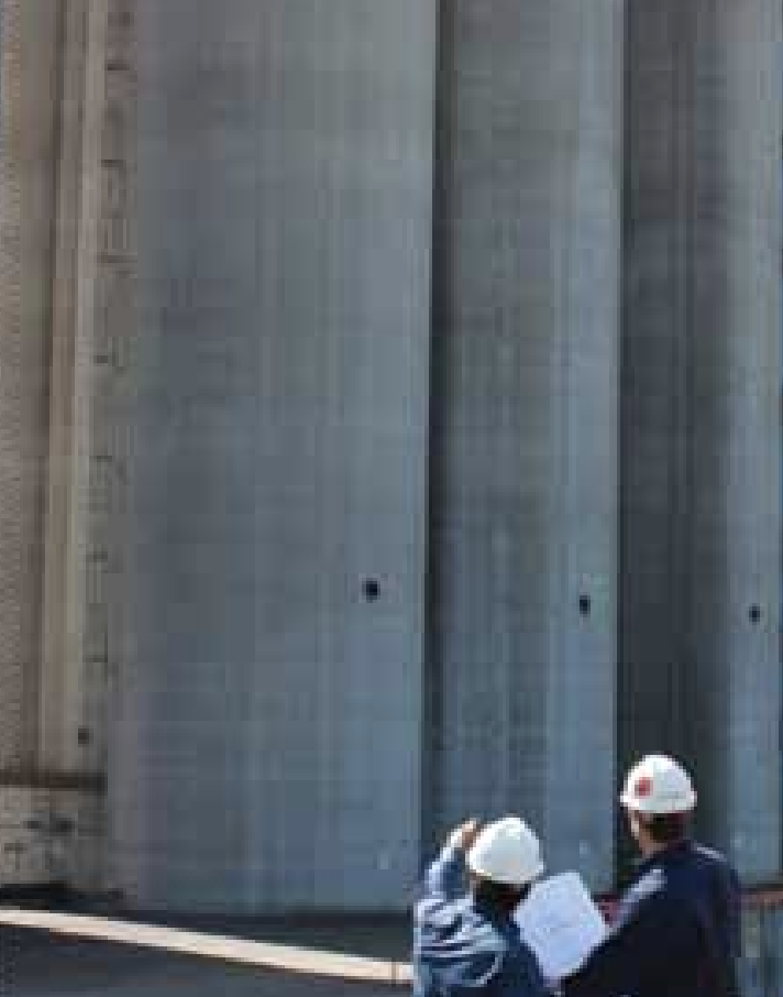
- Concrete silos. Generally speaking, when the silo diameter is larger than 9 m (30 ft), reinforced concrete silos become economically attractive, especially for bulk solids that are abrasive or hot, or if the storage structure will incorporate additional functionality, such as processing equipment. Concrete silos (Figure 14) have the following advantages over metal silos:
- Corrosion resistance. Concrete silos require less maintenance than metal silos because they are less prone to corrosion.
- Resistance to abrasive wear. Concrete silos are generally more resistant to abrasive wear effects than standard metal silos. They are also better able to withstand impact loads. A bulk solid’s abrasiveness against various materials of construction can be determined to assess liner or surface service life. Details can be found in Ref. 11.
- Ability to withstand non-uniform internal pressures. Reinforced steel construction can resist localized buckling and bending moments that can be detrimental to metal silos.
- No need for painting. External corrosion on metal silos will require periodic sanding, priming, and painting, whereas concrete silos do not.
- Lower cost for large diameters. Because metal silos require thick walls, reinforced concrete can be more economical for large-diameter tanks.
Structural design considerations. The bin must be designed to resist the loads applied to it by both the bulk solid and external forces, such as seismic, wind, or ancillary equipment loads. This is particularly important when designing for, or converting an existing bin to, mass flow, because unusually high localized loads may develop at the transition between the vertical section and the mass-flow hopper. Qualified structural engineers should calculate the complex loads that may be induced in the silo, bin, or storage vessel.
Closing thoughts
This step-by-step bin design approach has been effectively used for over 60 years in thousands of installations handling bulk solids, including fine chemical powders, granular resins, cohesive centrifuged wet cake, biomass, fragile cereal flakes, and abrasive ores (among others). Although it may be appealing to select a standard hopper design with a 45-deg. or 60 deg. angle, if it is not suitable for your bulk material, you will likely incur costs far beyond replacing the original equipment.
Literature Cited
- Jenike, A. W., “Storage and Flow of Solids,” Bulletin 123, Utah Engineering Experiment Station, Univ. of Utah, Salt Lake City, UT (1964).
- ASTM International, “Standard Test Method for Shear Testing of Bulk Solids Using the Jenike Shear Cell,” ASTM D-6128, ASTM, West Conshohocken, PA (2006).
- Mehos, G., “Designing Dust Collectors,” Chem. Eng. Progress, 107 (9), pp. 32–38 (Sept. 2011).
- Carson, J. W., “Sizing Hopper Outlets and Gates — Step-byStep,” Chem. Processing, Powder & Solids Annual (2000).
- Purutyan H., et al., “Increase Powder Flow via Gas Injection,” Chem. Eng. Progress, 102 (7), pp. 38–43 (July 2006).
- Royal, T. A., and J. W. Carson, “Fine Powder Flow Phenomena in Bins, Hoppers and Processing Vessels,” Presented at Bulk 2000: Bulk Material Handling Towards the Year 2000, London, U.K. (1991).
- Carson, J. W., “Feeding of Bulk Solids: A Review,” Bulk Solids Handling, 20 (3), pp. 279–282 (2000).
- Marinelli, J., and J. W. Carson, “Use Screw Feeders Effectively,” Chem. Eng. Progress, 88 (12), pp. 47–51 (Dec. 1992).
- Ebadat, V., “Managing Dust Explosion Hazards,” Chem. Eng. Progress, 105 (8), pp. 35–39 (Aug. 2009).
- National Fire Protection Association, “Standard for the Prevention of Fire and Dust Explosions from the Manufacturing, Processing, and Handling of Combustible Particulate Solids,” NFPA 654, NFPA, Quincy, MA (2013).
- Johanson, J. R., and T. A. Royal, “Measuring and Use of Wear Properties for Predicting Life of Bulk Materials Handling Equipment,” Bulk Solids Handling, 2 (3), pp. 517–523 (1982).