


Jenike & Johanson engineers have found that one key to proper screw feeder design is to provide an increase in capacity in the feed direction. When a screw’s design or pitch tolerances do not provide this increasing capacity along the length of the bin outlet, a screw will tend to withdraw material only from one end of the outlet, usually the back end.
The resulting small flow channel converts a mass flow bin to funnel flow which can lead to ratholing and arching with cohesive materials or flushing with fine powders. Moreover, torque increases when the screw has to convey material past stagnant material above it. Even higher torque will be required if the screw’s capacity decreases at any point, thus compacting material.
The length of screw that can be used under a hopper outlet is limited by fabrication tolerances. Exceeding that limit often makes it impossible to provide the correct increase in capacity. In turn this results in a poorly performing screw and unsatisfactory flow-even in a well-designed bin.
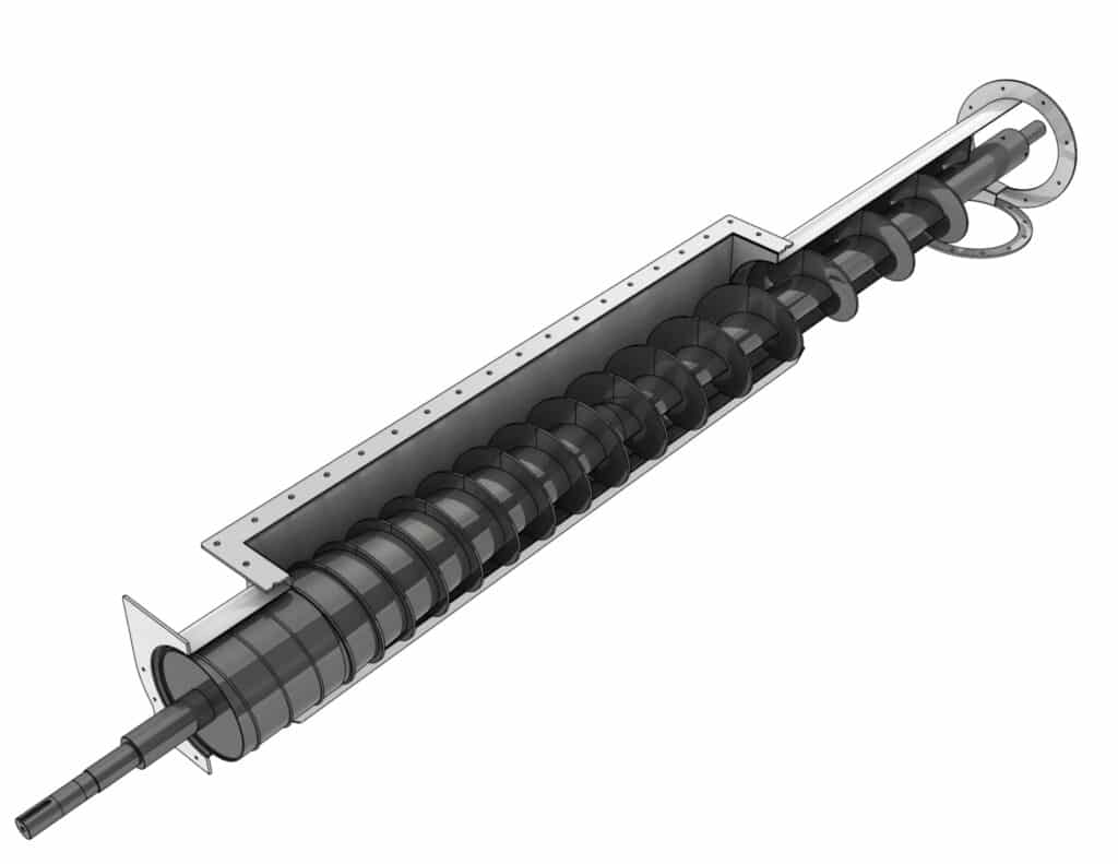
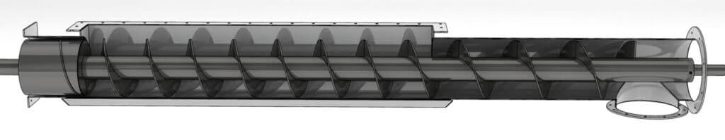
Jenike & Johanson engineers continue to develop customs designs for these kind of screws which include a cone section with constant pitch and an increasing pitch section followed by a constant pitch conveying section. Our design has been successfully used in hundreds of applications, handling such diverse materials as fly ash, terephthalic acid (a fine chemical powder), limestone, coal, sewage sludge and diatomaceous earth.
Even when the screw is properly designed, torque may be higher than expected unless the designer recognizes that torque is a function of the vertical solids pressure acting on the screw. This in turn is related to the material’s bulk density, wall friction, bin flow pattern, bin geometry and outlet width. For example, if the bin is a funnel flow design, the screw loads are much higher than if it were mass flow. Likewise, a vertical section above a screw (perhaps for a slide gate) increases solids pressure, as does increasing the bin outlet size. One common error is to design screws for a multiple screw live bottom feeder using loads that would occur on a single screw with a bin outlet only as wide as the screw.
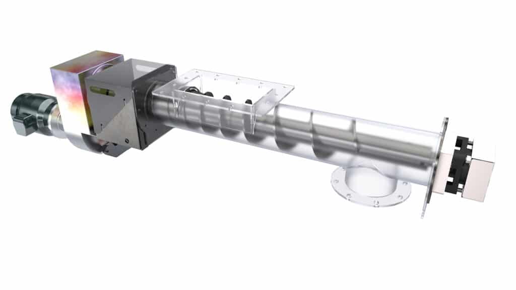
As with any piece of process equipment, the design of a screw must be appropriate for the material being handled and the process requirements. Obviously, screw speed must be kept low to minimize wear from abrasive materials. In addition, the conveying length past the outlet must be long enough to prevent free-flowing or fluidized materials from discharging when the screw is stopped. When a process requires a continuous flow stream, a small high-speed screw may provide the required smooth flow. Or perhaps a larger screw with multiple flights at the discharge point will work.
Cohesive and/or adhesive materials, such as tar sands or wet clay, require special attention being paid to the screw flight including shaft diameter and flight and trough finish. In addition, reverse flighting is often required after the discharge point. In order to ensure flow along the hopper walls, U-troughs are preferable to V-troughs when interfacing with a mass flow bin. In addition, it is essential that there be no lip at the hopper outlet which could impede flow. Since standard U-troughs have an inside dimension one inch larger than the screw diameter, setting the hopper outlet width equal to the screw diameter ensures no lip.