
In dust collection systems the rotary airlock allows continuous product discharge without having to turn off the vacuum to dump the accumulated material. Rotary airlocks are vital in pneumatic conveying systems, allowing the introduction of material into a pressure or vacuum stream with minimal loss of air.
Design & Construction
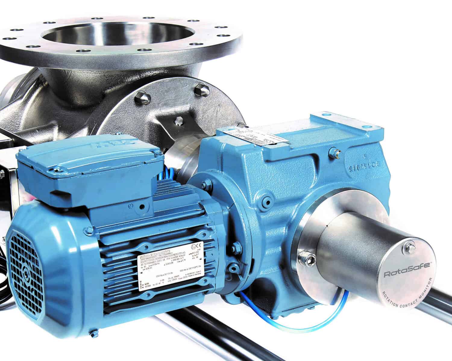
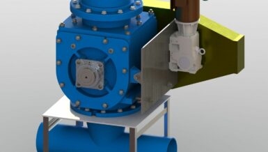
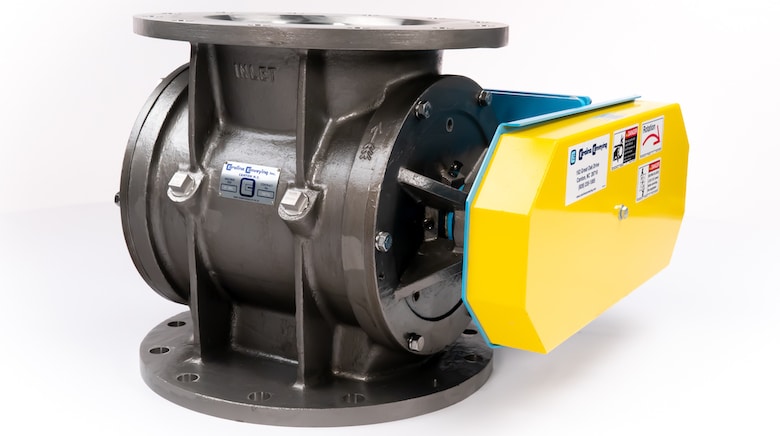
Rotary Airlock Valves have a heavy-duty cast housing that consists of a body and two end covers, an internal rotating rotor and a drive package. The body has an inlet and outlet which allows the material to enter and exit the valve. The rotor has a shaft with multiple vanes, and the ends of the shaft extend out through the housing to external bearings supported by the end covers. Inside the housing, the vanes radiate out away from the shaft to the housing. The space between the rotor vanes creates pockets that pick up material at the inlet and as the rotor rotates, transport the pockets of material to the outlet. The empty pockets then rotate back to the inlet to pick up more material. The drive package consists of a gearbox and electric motor and connects to the rotor shaft by a chain drive or may be directly coupled. The rotor rotates relatively slow, typical speeds are 22 rpm or less.
So how does the rotary valve provide an airlock? While the valve does not create a 100% seal, the leakage rate is greatly reduced when properly designed. The body and end covers must be of a heavy-duty design to withstand the pressure differential and precisely machined to very tight tolerances. A raised face on the inside of the end cover fits tightly and accurately into the body bore to ensure a good seal and proper alignment between the rotor and housing. The rotor needs a large shaft to prevent deflection and typically eight or more vanes. The rotor is precisely machined to fit tightly inside the housing. Typical clearances between the rotor and housing are 4 to 6 thousandths of an inch (0.004” to 0.006”) or roughly the thickness of a strand of coarse hair. These tight tolerances minimize air leakage as they allow the rotor to rotate with minimal clearances. The tighter the clearances, the less air that can leak through. The geometry of the body design is also important, as the more vanes and pockets that are contained within the housing and not exposed to the throats – the greater the seal.
Rotor Types & Selection
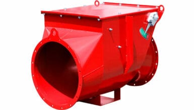
Carolina Conveying offers several different body styles, each that work best for certain applications. For this article, we are going to move on to the varying types of rotors and how to pick the best design based on the application. Proper rotor selection is a critical part of specifying a valve that will best suit the intended service, making a significant difference in the life of the valve and overall performance.
The two most common types are the Open End Rotor and Closed-End (Shrouded) Rotor. Refer to the photos of each. When viewing the open rotor from the shaft end, you will see multiple vanes radiating out creating ‘V’s or ‘U’s which are the pockets. The ends of the vanes are left open. If water was poured into the top pocket, it would simply run out the sides.
The Closed or Shrouded Rotor has round end discs that are welded to the shaft and ends of the vanes. Looking at the rotor from the end of the shaft, you will not see the ‘V’ pockets but instead a round disc. The ends of the vanes are closed off. Unlike the open rotor, water poured into the top pocket is retained by the end discs.
Numerous design options, materials of construction and varying rotor tips are available, from abrasion resistance to flexible tips.
Application specialists at Carolina Conveying will help you specify the correct rotary airlock for your system. Information vital to selecting the best valve includes material being handled, bulk density, particle size, material characteristics, moisture content, temperature range, equipment above and below the valve, pressure or vacuum levels and the desired discharge rate. They should have vast experience in handling all types of products in various types of systems. Selecting the correct rotary airlock valve, rotor, and design features is critical to ensure successful operation with minimal air leakage and downtime, along with maximum valve life.